In many digital signal processing algorithms, you often need to perform computations on complex numbers, and the most common of these is multiplication. In this article, we will implement complex number multiplication in VHDL.
However, in FPGAs and digital circuits in general, we don't have a specific physical or hardware-based representation for complex numbers.
More...
So, in this short article, I'm going to show you exactly how we can represent complex numbers on an FPGA and perform complex arithmetic operations effectively.
As I mentioned at the beginning, in a digital circuit – including FPGAs – there is no built-in physical or hardware-based mechanism to represent complex numbers.
For example, we don’t have a data type to directly define a signal as complex.
However, many signal processing algorithms require you to perform arithmetic operations like multiplication and addition on complex numbers.
Naturally, this raises the question: how can we handle these complex operations using digital circuits?
That’s exactly what I want to demonstrate in this article.
Toward the end, we’ll also look at an example using VHDL code to better illustrate the concept.
Representing Complex Numbers on an FPGA
As you know, complex numbers consist of two parts: a real part and an imaginary part.
For example, in the case of the complex number x shown here, it has a real part Xr and an imaginary part Xi, and it’s represented as:
X = Xr + jXi
Complex Multiplication: Real and Imaginary Parts
Now let’s assume we have another complex number Y and that we need to represent these two complex numbers in an FPGA and also perform a multiplication operation on them.
So, we want to multiply the two complex numbers X and Y and obtain a complex result, which we’ll call F.
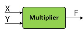
A complex multiplier: complex inputs X and Y, complex product F.
But how can we represent these complex input and output ports on an FPGA?
As I mentioned above in the article, there is no specific physical or hardware-based mechanism to represent complex numbers in FPGA design.
But before I explain how we can represent these complex numbers, we need to first simplify the multiplication on paper.

Expanding X × Y gives a real part (xr·yr − xi·yi) and an imaginary part (xr·yi + xi·yr).
Let’s go ahead and perform the multiplication of these two complex numbers on paper and simplify it.
When you multiply X with Y and rearrange the terms, you’ll get an expression like the one above.
Notice that the resulting complex number consists of two separate parts: a real part and an imaginary part.
I'll name the real part Fr and the imaginary part Fi. So, now our resulting complex number F clearly consists of a real part, Fr, plus an imaginary part, Fi.
One Signal for the Real Part, One for the Imaginary Part
Now, to represent these complex inputs and outputs on an FPGA, we use a straightforward method: for each complex signal or port, we define two separate signals in the FPGA.
So, the module we define will have the following ports:
For example, for the input signal X, we define two separate signals in the FPGA: one for the real part and one for the imaginary part.
We do the same for the input Y.
And for the output F, since it’s also a complex number, we define two signals: one for the real part and one for the imaginary part.
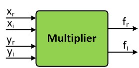
For complex number multiplication in VHDL, each complex port becomes two signals: xr, xi, yr and yi in, fr and fi out.
Looking at the equations we derived earlier, we have:
Fr = (Xr × Yr) - (Xi × Yi)
Fi = (Xr × Yi) + (Xi × Yr)
Now that we’ve simplified the math on paper, we're ready to implement this in hardware.
Complex Number Multiplication in VHDL: Example Code
Specifically, we'll use VHDL to write a piece of code describing a circuit with four input ports, where each pair corresponds to one of the complex inputs, and two output ports, which together represent the complex output.
Using the equations we've derived, we'll express each output port clearly in terms of these input signals.
Let’s take a look at the VHDL code that implements this multiplier so the concept becomes clearer.
library IEEE; use IEEE.STD_LOGIC_1164.ALL; use IEEE.NUMERIC_STD.ALL;entity Multiplier_Top is Port ( Clock : in STD_LOGIC; X_Real : in signed (7 downto 0); X_Imag : in signed (7 downto 0); Y_Real : in signed (7 downto 0); Y_Imag : in signed (7 downto 0); F_Real : out signed (15 downto 0); F_Imag : out signed (15 downto 0) ); end Multiplier_Top;architecture Behavioral of Multiplier_Top issignal X_Real_Int : signed (7 downto 0) :=(others=>'0'); signal X_Imag_Int : signed (7 downto 0) :=(others=>'0'); signal Y_Real_Int : signed (7 downto 0) :=(others=>'0'); signal Y_Imag_Int : signed (7 downto 0) :=(others=>'0'); signal F_Real_Int : signed (15 downto 0) :=(others=>'0'); signal F_Imag_Int : signed (15 downto 0) :=(others=>'0');begin F_Real <= F_Real_Int; F_Imag <= F_Imag_Int; process(Clock) begin if rising_edge(Clock) then X_Real_Int <= X_Real; X_Imag_Int <= X_Imag; Y_Real_Int <= Y_Real; Y_Imag_Int <= Y_Imag; F_Real_Int <= X_Real_Int * Y_Real_Int - X_Imag_Int * Y_Imag_Int; F_Imag_Int <= X_Real_Int * Y_Imag_Int + X_Imag_Int * Y_Real_Int; end if; end process;end Behavioral;
Our goal here is to multiply two complex numbers, X and Y, and place the resulting product into the complex output F.
Since these numbers are complex, we've defined two ports for each number: one for the real part and another for the imaginary part.
For X, we define two ports: Xr and Xi, which are input ports representing the real and imaginary parts of X.
In this example, I’ve defined them as signed 8-bit numbers, though you can adjust the bit-width as needed for your application.
We do the same for Y.
And for the output F, we define its type as signed with a bit-width of 16.
Why 16 bits?
Because the output is the product of two 8-bit numbers, and multiplying two 8-bit numbers naturally results in a 16-bit wide result.
To follow the Standard Coding Template for FPGA, we also define internal signals corresponding to each of these input and output ports.
At the beginning of the process block, we register the input signals into these internal signals.
Now, we simply implement the two equations we derived earlier. For the real part of the output F, we assign (Xr × Yr) − (Xi × Yi). For the imaginary part of the output, we assign (Xr × Yi) + (Xi × Yr).
This way, we complete the implementation of the complex number multiplication in the FPGA.
F_Real_Int <= X_Real_Int * Y_Real_Int - X_Imag_Int * Y_Imag_Int; F_Imag_Int <= X_Real_Int * Y_Imag_Int + X_Imag_Int * Y_Real_Int;
In case you synthesize this code and realize the maximum achievable clock frequency isn't as high as you'd like, you can apply pipeline techniques to these two calculation lines, significantly improving the speed and performance.
Practical Tip!
In case you synthesize your code and realize the maximum achievable clock frequency isn't as high as you'd like, you can apply pipeline techniques in order to significantly improving the speed and performance.
I hope this guide to complex number multiplication in VHDL was helpful to you.