In this article, we're going to discuss fixed-point arithmetic in FPGA designs, one of the core concepts you'll need when implementing digital signal processing algorithms on an FPGA.
Specifically, today I'll focus on how to represent and perform calculations with fractional numbers within FPGA designs.
More...
This topic is one of the most important and foundational skills you need to implement DSP algorithms on an FPGA.
So, the first question is: how can we represent fractional numbers on an FPGA, and how can we perform arithmetic operations with them?
Floating-Point vs Fixed-Point: Two Ways to Represent Fractions
In general, there are two methods to represent fractional numbers.
Floating-Point Representation
The first method is Floating-Point representation, which provides very high precision for fractional numbers.
This method follows standards developed by the IEEE, and there are two primary formats: 32-bit and 64-bit. These formats allow us to represent fractional numbers with extremely high accuracy.
However, when you're aiming to implement a digital signal processing algorithm on an FPGA, you'll encounter some significant challenges with Floating-point representation.
The first challenge is that implementing Floating-Point arithmetic on an FPGA is inherently complex.
The second issue is that it requires a significant amount of hardware resources.
And finally, it can slow down your circuit, and speed is usually one of your primary design criteria.
Why Fixed-Point Is Preferred for FPGA DSP
Because of these limitations, another representation method called Fixed-Point has become widely used for most DSP algorithm implementations on FPGAs.
One of the key advantages of Fixed-Point representation is that it consumes fewer hardware resources on the FPGA.
Additionally, circuits designed using Fixed-Point arithmetic are typically much faster than those designed with Floating-Point.
Due to these two major advantages, Fixed-Point representation is the preferred approach for most FPGA-based digital implementations.
Now, let’s dive deeper into this method and how we can implement it on an FPGA.
Fixed-Point Arithmetic in FPGA: How the Binary Point Works
Let’s start by exploring the concept of Fixed-Point representation with a question.
Take a look at this binary number. What decimal value do you think it represents?

The 7-bit pattern 1001010: what decimal value does it represent?
Well, probably all of you are calculating based on the positional values of the binary digits, and you'd say this number equals 74.
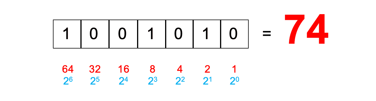
Read as an unsigned number, 1001010 equals 74 (64 + 8 + 2).
But what if I told you this binary number is actually a signed number? What would you do then?
In fact, let's say this number is represented using two's complement format, making it a signed binary number.
Since it’s a signed number and the sign bit is 1, we know that the value is negative.
So, to calculate its value, since we know it’s a negative number, one approach is to find the two’s complement of the number, and then place a minus sign next to it.
If you do this, you’ll find that the decimal value of this number is -54.

Read as a two's complement signed number, the same bits equal -54.
So, with a single binary number, we’ve been able to interpret two different decimal values: 74 as an unsigned number, and -54 as a signed number.
Now, let me ask my question again about this same binary number. What decimal number does it represent?
Now, suppose I place a binary point in this position here.

The same bits with a binary point placed after the fourth bit.
If we interpret the number again, we need to calculate the weights of each binary position relative to the binary point.
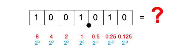
Bit weights relative to the binary point: 8, 4, 2, 1 to the left and 0.5, 0.25, 0.125 to the right.
To the left of the binary point, we have positions valued at 1, 2, 4, and 8, and to the right of the binary point, we have positions valued at 0.5, 0.25, and 0.125.
Under this new interpretation, the integer part of the number represents 9, and the fractional part represents 0.25.
Therefore, the value of the number is 9.25.
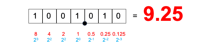
With three fractional bits, 1001.010 equals 9.25 (8 + 1 + 0.25).
What I wanted to highlight with this example is that the decimal value represented by a binary number depends entirely on how we interpret it.
Whether it's signed or unsigned, and where we position the binary point, fundamentally influences its value.
In Floating-Point representation, where numbers can be 32-bit or 64-bit, the location of the binary point isn’t fixed. Instead, it’s determined dynamically based on the value stored in the register.
But in Fixed-Point representation, as the name suggests, the location of the binary point is fixed and predefined.
For example, you might decide that a register has 3 fractional bits, meaning the binary point is fixed after the third bit.
The Binary Point Exists Only in Your Mind
You might now be wondering: Do we actually have any physical mechanism or hardware inside the FPGA to specify the location of the binary point?
We know we have registers, and we can store any binary number in a register, but how exactly do we indicate the binary point's position? Is there a special hardware component or physical representation for the binary point itself?
The answer to this question is no. In digital implementations, we cannot physically represent the binary point.
So, where is the binary point?
The answer is: the binary point exists in your mind.
As the designer, you decide where the binary point is located within a register.
Once you define its position, you need to consistently account for it throughout your implementation process.
The s.m.n Notation for Fixed-Point Formats
To clarify this concept further, let me introduce a method for analyzing Fixed-Point designs on paper.
One way to represent and analyze Fixed-Point registers and operations is a method I call the s.m.n notation.
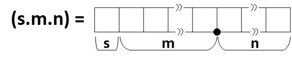
The s.m.n notation: s is the sign bit, m the integer bits and n the fractional bits.
In this notation, we use s to indicate the sign bit. If s is present, it means the register or signal is signed; if not, it's unsigned. m represents the number of integer bits, and n represents the number of fractional bits.
For instance, if we have an 8-bit signed register and we want to indicate it has 4 fractional bits, we represent it as s.3.4.

An 8-bit signed register with 4 fractional bits is written s.3.4.
Here, the 4 indicates 4 fractional bits, the 3 indicates 3 integer bits, and the s indicates the sign bit. Notice that 1 (sign bit) + 3 (integer bits) + 4 (fractional bits) totals 8 bits.
Similarly, if we have a 6-bit unsigned register with 2 fractional bits, we represent it as 4.2.
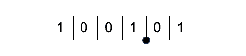
A 6-bit unsigned register with 2 fractional bits is written 4.2.
The 4 represents the 4 integer bits, and the 2 represents the 2 fractional bits. Since the number is unsigned, we don't include the s symbol.
To better understand Fixed-Point representation and its practical considerations, let’s look at an example of performing Fixed-Point addition.
Fixed-Point Addition: Aligning the Binary Points
When adding two fractional numbers on paper, you normally align their decimal points. The same principle applies in FPGA implementations.
To perform Fixed-Point addition correctly, you must line up the binary points.
For example, suppose we want to add these two registers you see below.
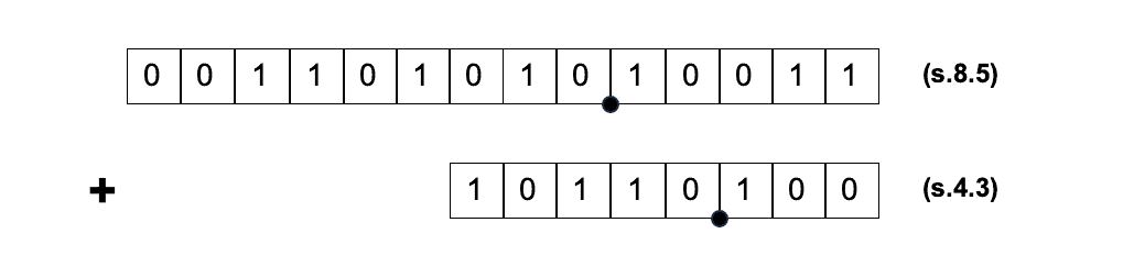
Two signed fixed-point registers to add: an s.8.5 value and an s.4.3 value.
Both are signed registers, but the first register has five bits to the right of the binary point (fractional bits), while the second one has three fractional bits.
Keep in mind that the binary points are not physically present —they exist only in our minds.
For the first register, we assume it has 5 fractional bits, meaning its fractional part can be represented using 5 bits. For the second register, the fractional part is represented using 3 bits.
If we want to add these two registers in a circuit, the problem is that the number of fractional bits in the two registers isn’t the same.
This mismatch would result in an incorrect sum.
To resolve this, we need to equalize the number of fractional bits.
To do this, we add two zero bits to the right of the second register. This adjustment aligns the binary points of the two registers.
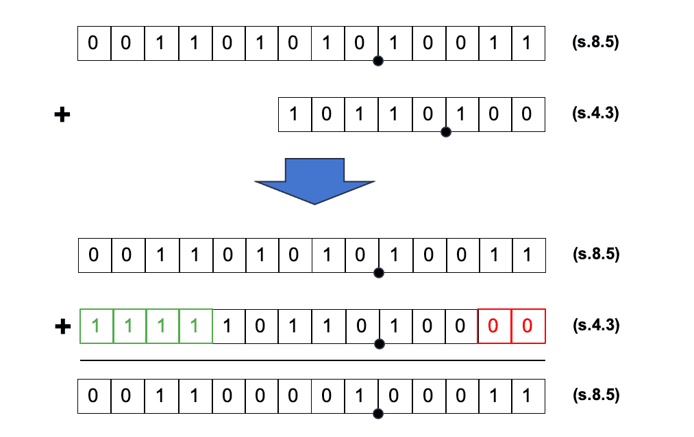
Aligning the binary points: two zeros (red) are appended to the s.4.3 value, and VHDL sign-extends it (green) before the addition.
You can use the concatenation operator to add bits to the right of a signal, which I’ve explained in one of my previous tutorials on VHDL.
Regarding the integer parts, you might notice that they're not equal either.
However, you usually don't need to explicitly take action for integer bits in VHDL.
When adding two signed numbers of different bit-widths, VHDL automatically performs sign extension on the shorter number, replicating the sign bit as necessary so that both numbers have equal widths.
This ensures that the addition is performed correctly, and the binary points are aligned.
So, you can safely perform the addition without issues, correctly handling the binary points in your Fixed-Point arithmetic.
So, that's it for today.