In this article, I want to talk about overflow detection in VHDL and how to control overflow in FPGAs.
In many circuits, especially those used to implement digital signal processing algorithms, you'll need to detect overflow at various stages and handle it appropriately.
More...
So, in this article, we'll discuss both how to detect overflow and how to control it.
Carry vs Overflow: Why They Are Not the Same
Let's talk a bit about Carry and Overflow and see exactly what they are.
The issue is that many engineers working in the field of digital system design and implementation get confused about the concepts of Carry and Overflow, and many think they're the same thing.
But in two's complement representation, these two concepts are not related at all, and they are two completely separate topics, which we will examine together in this article.
In digital design, it’s important to detect overflow and, when necessary, control it. We’ll examine this topic with examples in the upcoming paragraphs.
So, what are carry and overflow?
To better explain this, let’s begin with an example.
Carry and Overflow in Unsigned Number Addition
Let’s say we want to add two 4-bit unsigned numbers. The range of a 4-bit unsigned number is from 0 to 15.
For instance, if we add 9 and 12, the expected result is 21, but 21 is outside the range of values that can be represented in a 4-bit number.
Therefore, we encounter an overflow.
If we perform this addition on paper, we’ll see that an extra bit is generated at the end. This extra bit is called the carry.
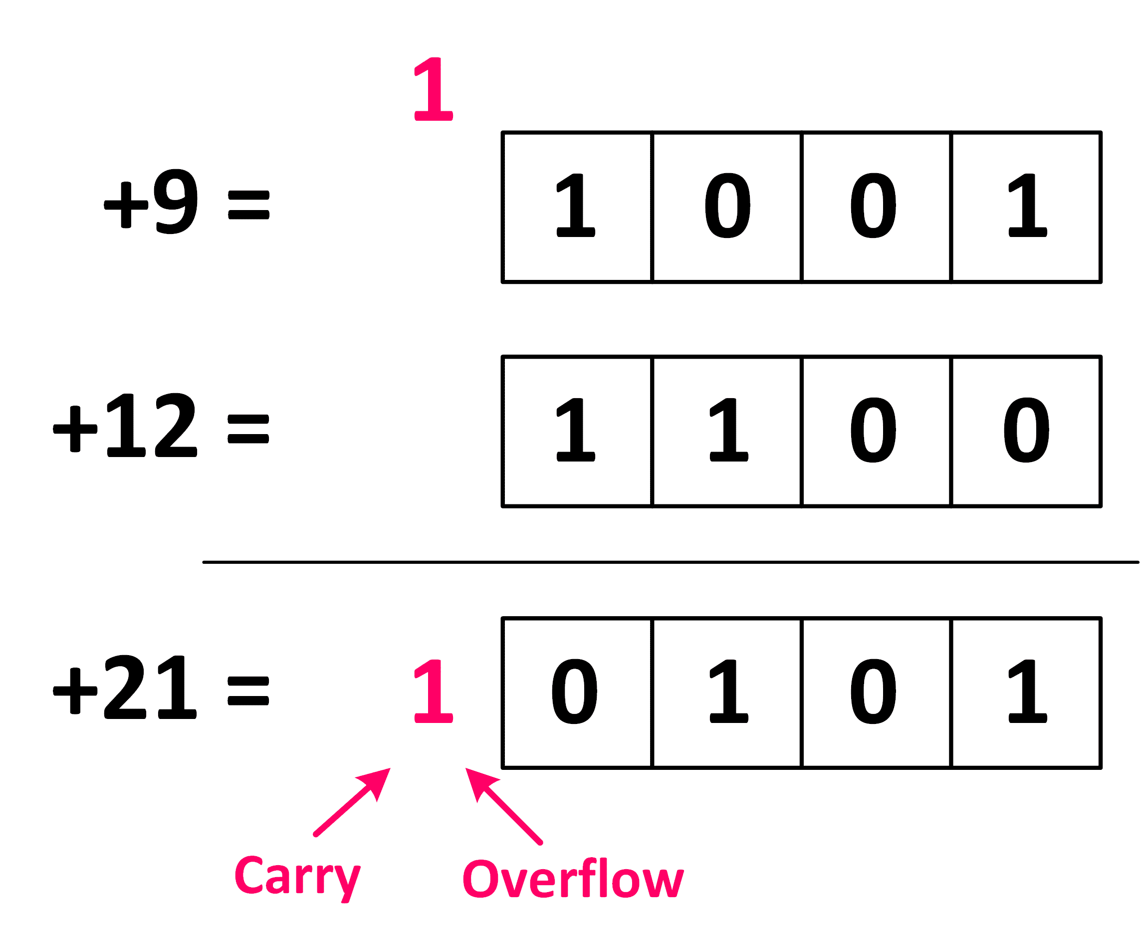
Unsigned 4-bit: 9 + 12 = 21 does not fit, so the extra bit is both the carry and the overflow.
In the case of unsigned addition, carry and overflow are essentially the same. That is, whenever we have a carry — meaning the extra bit generated is 1 — we also have an overflow, and vice versa.
This is why, when you first learned about this topic, the example likely involved unsigned numbers, leading many to assume that carry and overflow are the same.
Carry and Overflow in Signed Number Addition
However, the situation is entirely different for signed numbers.
Let’s say we want to add two 4-bit signed numbers. The range of values that can be represented in 4-bit signed numbers is from -8 to 7.
Now, if we add 5 and -6, the result is -1, which falls within the valid range. Therefore, no overflow occurs.
If we perform the addition, we’ll also see that there’s no extra bit generated, meaning there’s no carry either.
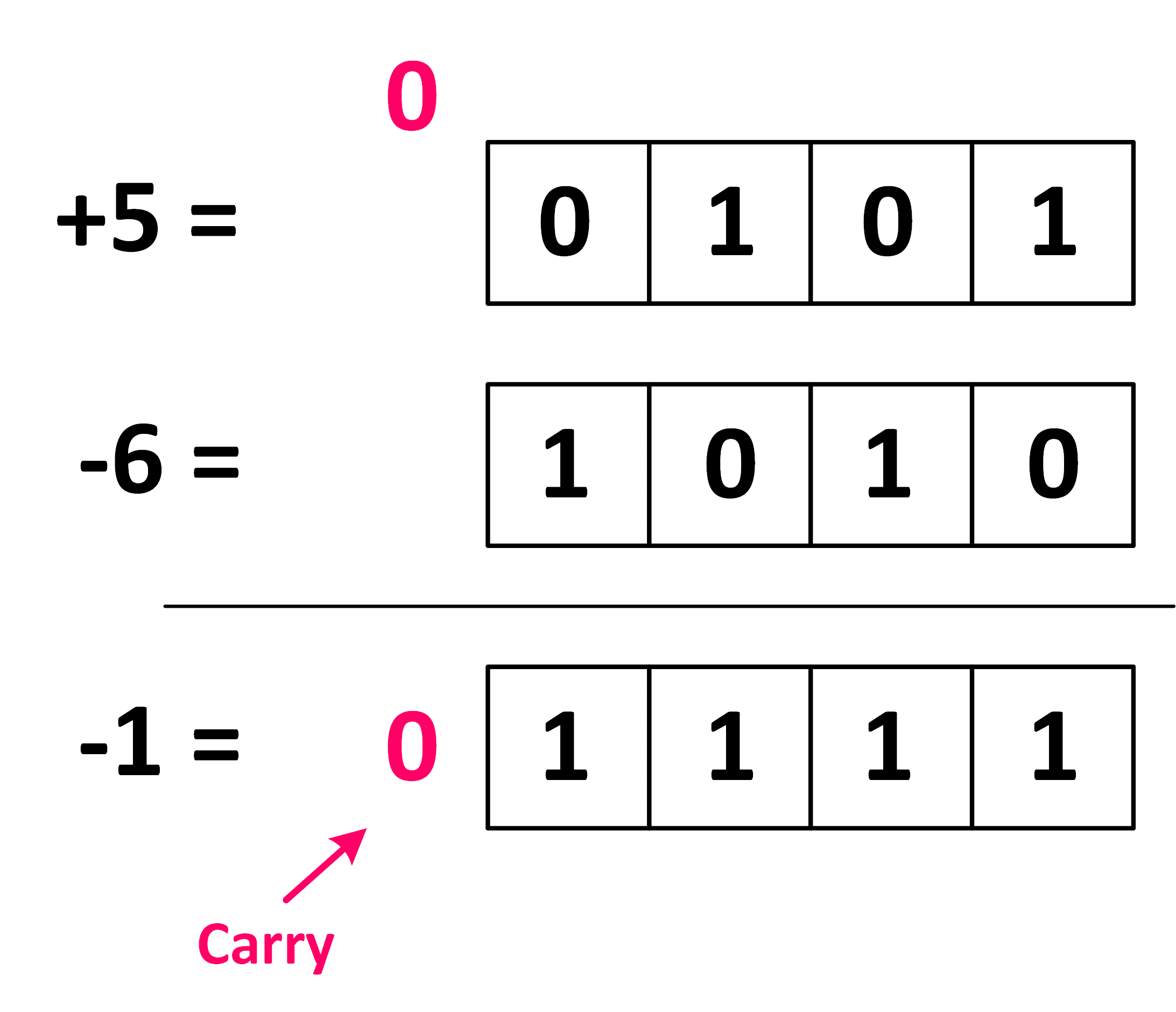
Signed 4-bit: +5 + (−6) = −1, with no carry and no overflow.
Let’s look at another example.
Suppose we add 5 and -3. The result is 2, which is within the range, so no overflow occurs.
However, if we perform this addition on paper, we’ll notice that an extra bit is generated. This means there is a carry.
So, in this case, we don't have overflow, but we do have carry.
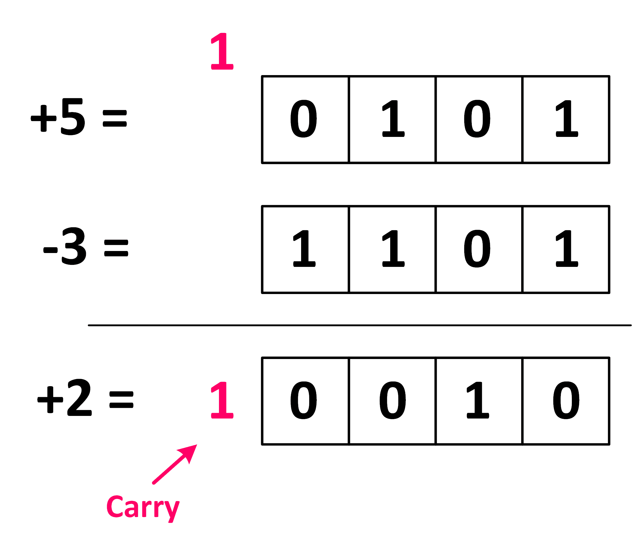
Signed 4-bit: +5 + (−3) = +2, with a carry but no overflow.
Now let’s examine another example: -6 and -5, which equals -11. -11 is outside the range of -8 to 7, so we have an overflow.
If we perform the addition on paper, we’ll also see that an extra bit is generated, meaning we also have a carry.
In this case, we have both carry and overflow.
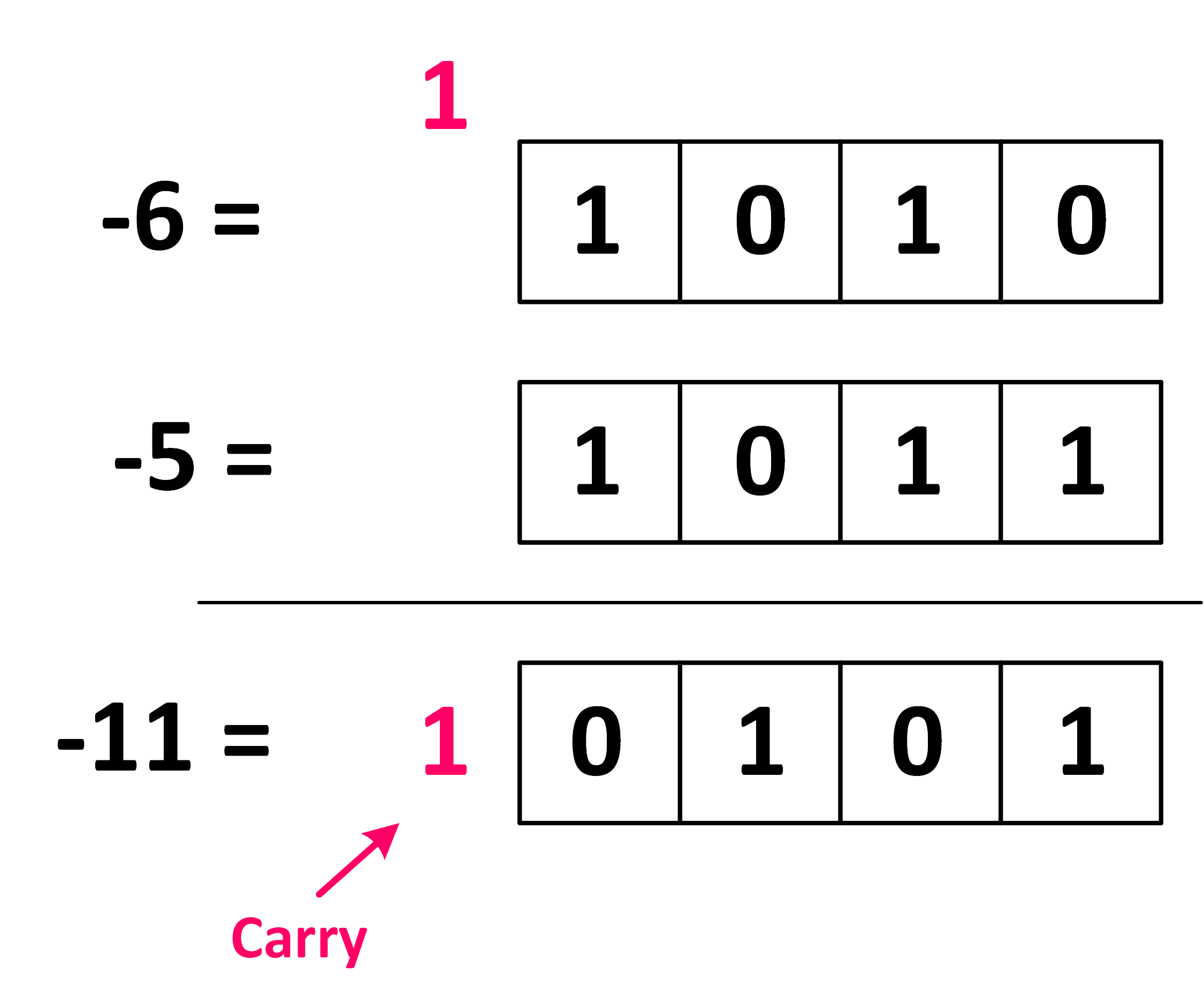
Signed 4-bit: −6 + (−5) = −11, with both a carry and an overflow.
Finally, consider the addition of 6 and 5, which equals 11. 11 is outside the range, so we have an overflow.
However, if we perform the addition on paper, we’ll see that no extra bit is generated, meaning there’s no carry.
So in this example, overflow existed, but carry did not.
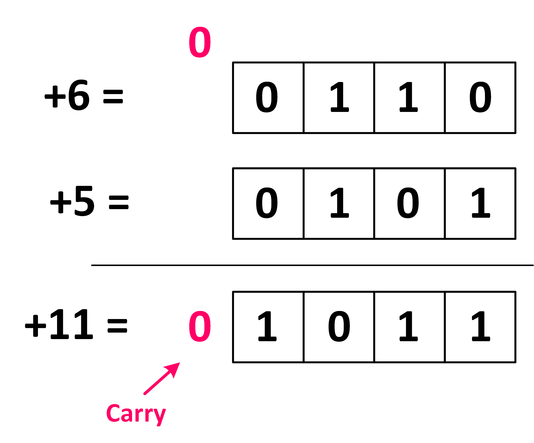
Signed 4-bit: +6 + (+5) = +11, an overflow without a carry (the 4-bit result reads as −5).
As you can see from these examples, various scenarios can occur when adding signed numbers: We can have both carry and overflow, we can have neither of these two, and we can have only one of these two.
Therefore, when dealing with signed numbers, carry and overflow are completely independent concepts and are not related to each other.
General Definition of Carry and Overflow
Now let’s provide a general definition of carry and overflow.
When you add two n-bit numbers, the bit at position n+1 is the carry, which can be either 0 or 1. If the result of the addition falls outside the representable range for those numbers, overflow occurs.
This is a general definition and applies to both signed and unsigned numbers.
However, detecting and handling carry and overflow differs for signed and unsigned numbers. Let’s now discuss this in detail.
First, let’s see how to detect carry and overflow in unsigned numbers.
To detect carry and overflow in unsigned numbers, the method we use is as follows: place the sum of two n-bit numbers into an (n+1)-bit signal. The bit at position n+1 of the sum, which is the most significant bit (MSB), indicates both carry and overflow.
Overflow Detection in VHDL: Unsigned and Signed
Let’s go through an example of overflow detection in VHDL to clarify this.
Unsigned Addition: Carry and Overflow from the MSB
Suppose we want to add two 4-bit unsigned numbers in VHDL. As we mentioned, the result must be stored in an (n+1)-bit signal, which in this case is 5 bits.
Therefore, the signal Sum here is 5 bits wide.
Sum <= resize(A,5) + B; Carry <= Sum(4); Overflow <= Sum(4);
To comply with the addition assignment rule in VHDL, we need to extend the width of one of the signals, A or B, to 5 bits using the Resize function.
So, we add A and B, which are both 4 bits, and store the result in a 5-bit signal called Sum. As I mentioned earlier, the most significant bit (MSB) of the signal Sum serves as both the carry and the overflow.
Therefore, Sum(4) represents both the carry and the overflow.
Signed Addition: Overflow from the Two MSBs
Now let’s move on to calculating carry and overflow for signed numbers.
For signed numbers, we again place the sum of two n-bit numbers into an (n+1)-bit signal.
However, this time, the overflow is determined by the XOR of the two most significant bits (MSBs) of the Sum, and the carry is calculated as the XOR of the MSBs of the inputs and the Sum.
To clarify this further, let’s look at an example in VHDL.
Suppose we want to add two 4-bit signed numbers. As mentioned earlier, we store the result in a 5-bit signal, which we have named Sum here.
Sum <= resize(A,5) + B; Carry <= Sum(4) xor A(3) xor B(3); Overflow <= Sum(4) xor Sum(3);
As you can see, the XOR of the MSB of Sum and the MSBs of the inputs, A and B, together form the carry.
The XOR of the two MSBs of Sum — specifically Sum(4) and Sum(3) — determines the overflow.
This method of overflow detection in VHDL allows you to easily detect overflow and carry in your code and take appropriate action when necessary.
Overflow Handling Methods: Wrapping vs. Saturation
So, the key question is: how do we handle overflow when it occurs?
Wrapping Method
There are two general methods for handling overflow. The first is called the wrapping method, where we don’t control the overflow at all and simply allow the natural behavior of two's complement numbers to occur.
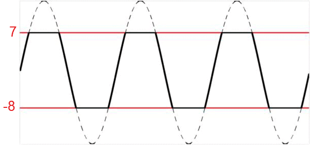
For example, in this waveform, we’ve plotted a sine signal within a representable range. The two red lines indicate the representable range of the signal.
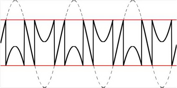
Wrapping: when the sine (dashed) leaves the range between the red lines, the value wraps around to the other end (solid line).
You can see that the sine waveform exceeds this range at certain points, causing overflow.
Since we’re not controlling the overflow, when it occurs in two's complement numbers, values wrap around.
For example, when an overflow occurs at the upper end of the range, the value wraps back to the lower end, and vice versa.
The final waveform, shown as a continuous black line, illustrates how the signal looks after wrapping.
Saturation Method
The second method for handling overflow is called saturation. In this method, when an overflow occurs, we limit the output to the maximum or minimum value within the representable range.
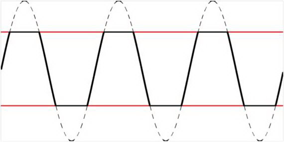
Saturation: the output is clamped to the maximum or minimum value, so it stays close to the original sine.
For instance, in this sine example, when the signal was about to exceed the upper limit, we saturated it at the maximum value instead of letting it wrap around.
Similarly, for the lower end of the range, we saturated the signal at the minimum value.
As you can see, this results in a waveform that more closely resembles the original sine signal, with less error compared to the wrapping method.
In practice, the saturation method is the method that we use if we decide to control overflow.
Saturation Arithmetic in VHDL: Example Code
Now, as the final topic, let’s look at how to detect and handle overflow using the saturation method in VHDL.
Suppose we have a signal that stores the sum of two numbers, and this signal is 4 bits wide, meaning the range of values that can be represented is from -8 to 7.
Saturating a 4-bit signed sum to its range of −8 to +7.
We want to detect overflow in this sum and handle it using the saturation method.
To do this, we can write code like the example shown here.
Sum <= resize(A,5) + B; Sum_Saturated <= Sum(3 downto 0);if (Sum(4) = '0' and Sum(3) = '1') then Sum_Saturated <= to_signed(7,4); end if;if (Sum(4) = '1' and Sum(3) = '0') then Sum_Saturated <= to_signed(-8,4); end if;
In this code, we add two 4-bit inputs, A and B, and store the result in a 5-bit signal named Sum. We then saturate Sum and store the saturated value in another 4-bit signal called Sum_saturated.
If no overflow occurs, the correct result is contained within the lower 4 bits of Sum. We can extract these 4 bits and store them in Sum_saturated.
However, if overflow does occur, the XOR of the two most significant bits of Sum will be 1.
If the XOR of the two most significant bits of Sum is one, it means that the two most significant bits are different.
Now, if Sum(4) is 0 and Sum(3) is 1, this indicates an overflow from the upper end. In this case, to saturate the output, we set the value of Sum_saturated to the maximum representable value, which is 7.
If Sum(4) is 1 and Sum(3) is 0, this indicates an overflow from the lower end. In this case, we set the value of Sum_saturated to the minimum representable value, which is -8.
Using this method, you can detect overflow in the sum of two 4-bit numbers, handle it using saturation methods, and store the result in Sum_saturated.
I hope you found this guide to overflow detection in VHDL helpful.