In this article, I want to discuss how to represent signed numbers on an FPGA and implement signed arithmetic in VHDL.
In many applications, you’ll need to work with signed numbers and perform operations like addition, subtraction, multiplication, and division on them.
More...
This becomes particularly important if you plan to dive into implementing digital signal processing (DSP) algorithms as you progress in your FPGA learning journey.
Understanding how to handle signed numbers is one of the foundational topics you’ll need to master for such implementations.
Let me start by giving you an overview of the methods used to represent signed numbers.
Three Ways to Represent Signed Numbers in Binary
If you recall from your digital logic courses, there are generally three methods for representing signed numbers.
Sign and Magnitude Representation
The first method is called Sign and Magnitude.
In this approach, positive numbers are represented as usual in binary, but for negative numbers, the most significant bit (MSB) is used as the sign bit.
A 0 in the MSB indicates a positive number, while a 1 indicates a negative number. The remaining bits are called magnitude bits and represent the absolute value of the number.
For example, to represent -6, we write the binary equivalent of 6 in the magnitude bits and set the sign bit (the MSB) to 1 to indicate that it’s negative.
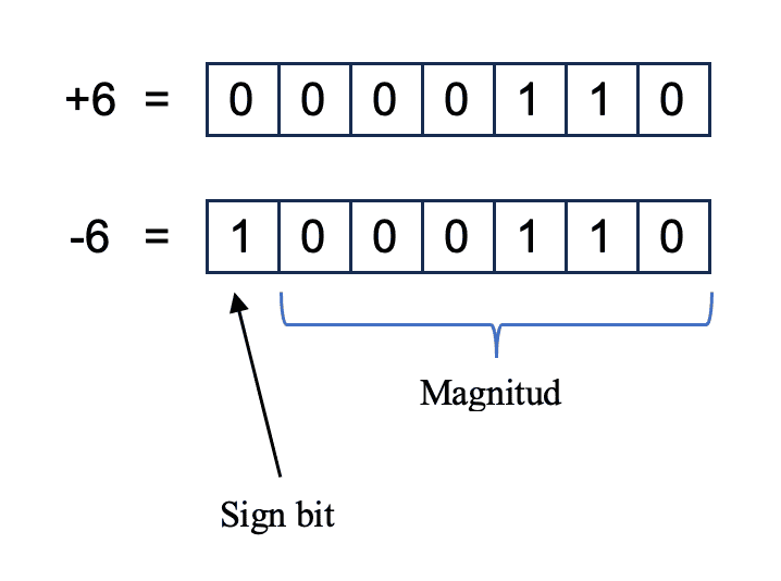
+6 and -6 in sign and magnitude: only the sign bit (MSB) changes.
However, this method is not very useful for implementing operations like addition or subtraction.
Subtraction, in particular, becomes very difficult to implement with this representation, and as a result, it is rarely used in practice.
Another drawback of the Sign and Magnitude representation is that it allows two representations for zero.
For instance, in a 5-bit system, the two values you see here both represent zero.
00000 = 10000 = zero
This redundancy is another reason why the Sign and Magnitude method is not commonly used.
One's Complement Representation
The second method is called One's Complement.
Similar to the previous approach, positive numbers are represented normally in binary, but negative numbers are represented by taking the one’s complement of the positive value.
To compute the one’s complement, you simply invert all the bits of the positive number.
In this example, you again see the numbers 6 and -6. To get -6 from 6, we've inverted every single bit.
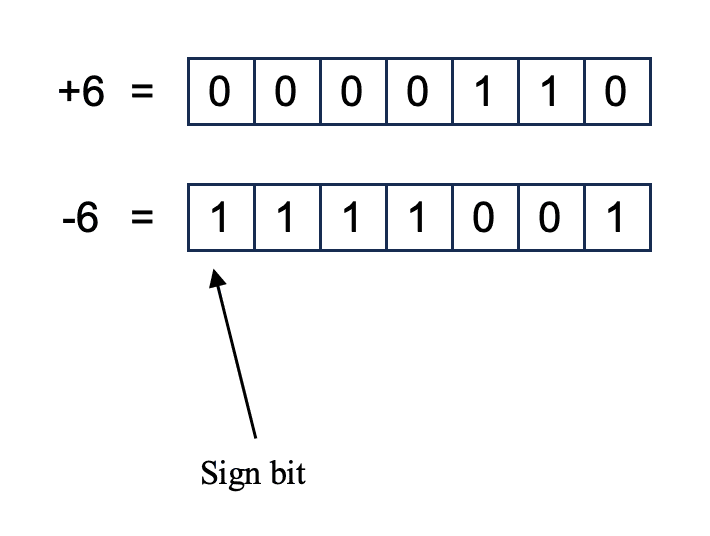
+6 and -6 in one’s complement: every bit of +6 is inverted.
In this representation, the most significant bit still acts as the sign bit, and a one in this position indicates a negative number.
However, one’s complement also suffers from the same issue of having two representations for zero. If all the bits are 0, or all the bits are 1, both represent zero.
00000 = 11111 = zero
This makes the implementation of arithmetic operations somewhat cumbersome in practice.
Two's Complement Representation
The third and most popular method is called Two's Complement.
In two's complement, similar to before, positive numbers are represented in the standard binary form. However, negative numbers are represented by calculating the two's complement of the corresponding positive number.
There are two mental methods for calculating the two's complement of a number.
The first method is to calculate the one's complement and then simply add one to it.
The second method is to start from the rightmost bit of the number, copy all zeros until you encounter the first one, copy that first one as well, and then invert all of the remaining bits.
For example, let’s look at the number 6 and its two’s complement representation for -6.
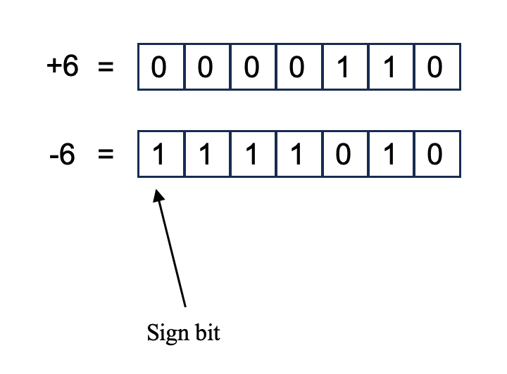
+6 and -6 in two’s complement: invert every bit of +6, then add 1.
As with the previous methods, the MSB is the sign bit, and a 1 in the MSB indicates a negative number.
The biggest advantage of the two’s complement method is that subtraction is very easy to implement. In fact, you can perform subtraction using the same hardware circuit that performs addition.
Another advantage is that every number has a unique representation.
Unlike the previous two methods, where zero had two representations, two’s complement eliminates this issue entirely. Zero has only one representation in two’s complement.
Two's Complement Range and Intermediate Overflow
One of the lesser-known advantages of representing signed numbers using the two's complement system is that you can add multiple signed numbers together, and as long as you're sure the final result of this addition fits within the range of values that can be represented, then overflows occurring during intermediate additions won't cause an error in the final result.
Let me explain this with an example.
In a two’s complement system, if you use n bits to represent numbers, the range of values that can be represented is from -2^(n-1) to 2^(n-1) - 1.
For instance, in a 3-bit two’s complement system, the range is from -4 to +3.
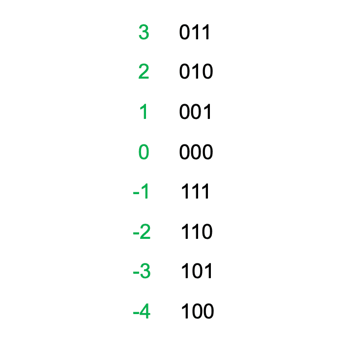
All eight values of a 3-bit two’s complement number, from -4 (100) to +3 (011).
Notice that the smallest number (-4) and the largest number (+3) are not symmetric; there is always a difference of one unit between them.
As another example, in a 4-bit two's complement system, the smallest number is -8, while the largest is +7.
Now let's suppose we want to add these five numbers: 2, 3, -4, 2, and -5. We know the final answer is -2, which fits within our 3-bit representation.
2 + 3 - 4 + 2 - 5 = -2
Because we know the final result is within the valid range, intermediate overflow occurrences won't cause a problem.
For example, when adding 2 and 3, the intermediate result is 5, which is outside the 3-bit range.
Here an overflow occurs, but this overflow doesn't affect the correctness of our final result because we already know the final sum is within range.
This is a subtle yet important benefit. It may not be something you use every day, but when you do use it, it can save significant FPGA resources.
Because of these unique advantages, the two’s complement system is widely used in digital systems for signed number calculations.
In fact, most digital systems that handle signed arithmetic rely on this representation. In VHDL, two’s complement is the default method used for signed number representation.
Implementing Signed Arithmetic in VHDL
Let’s now take a look at how we can perform signed arithmetic in VHDL and implement two’s complement on an FPGA.
Signed vs Unsigned Types in numeric_std
To work with signed numbers and perform arithmetic operations in VHDL, I recommend using the unsigned and signed types to define all your FPGA's internal signals and ports.
You may already know that VHDL offers several ways to represent signed numbers and perform arithmetic, but the method I’m sharing here is the one recommended by Xilinx.
Using this method ensures you can comfortably perform basic signed arithmetic now, and also easily extend your designs into digital signal processing algorithms in the future without confusion or ambiguity.
To use the unsigned and signed types, you need to include the numeric_std package from the IEEE library at the top of your VHDL code.
use ieee.numeric_std.all;
Once the package is included, you can define signals using either the unsigned or signed type.
For example, to define a signal named x as signed, you can write:
signal X : signed(7 downto 0) := (others=>'0');
You can also specify the width of the signal and give it an initial value.
Now, you might wonder: when should you use signed, and when should you use unsigned?
The rule of thumb is simple: if the signal will be involved in signed arithmetic operations, use the signed type. Otherwise, use unsigned.
Example: 16-Bit Signed Adder with Overflow Detection in VHDL
Let's illustrate this with a simple example. Here we'll implement a 16-bit signed adder.
library IEEE; use IEEE.STD_LOGIC_1164.ALL; use IEEE.NUMERIC_STD.ALL;entity Signed_Adder is Port ( A : in signed (15 downto 0); B : in signed (15 downto 0); Sum : out signed (15 downto 0); Overflow : out STD_LOGIC ); end Signed_Adder;architecture Behavioral of Signed_Adder issignal Sum_Int : signed (16 downto 0) :=(others=>'0');begin Sum_Int <= Resize(A,17) + B; Sum <= Sum_Int(15 downto 0); Overflow <= Sum_Int(16) xor Sum_Int(15);end Behavioral;
For simplicity, we won't consider the carry-in input, but we'll include an overflow output signal to detect overflow conditions.
At the beginning of your code, you need to include the numeric_std package, as shown above. This allows you to access the signed and unsigned types, as well as many other useful features.
In the Entity declaration, I’ve defined two 16-bit signed inputs, A and B, and a 16-bit signed output, Sum. I’ve also added a 1-bit STD_Logic output named Overflow to indicate whether the addition caused an overflow.
To compute the sum and detect overflow, I’ve defined a 17-bit internal signal named Sum_int of type signed. This allows us to store the result of A + B without losing any extra bit if it overflows.
To follow VHDL's addition assignment rules, we must also ensure at least one of the signals involved in the addition matches the width of the left-hand side signal, Sum_int.
Since A and B are originally 16 bits and Sum_int is 17 bits, I've resized signal A to 17 bits using the resize function.
The resize function allows you to easily adjust the width of signals during assignment. Here, I've resized the 16-bit signal A to 17 bits to comply with VHDL addition assignment rules.
After adding A and B and storing the result in the 17-bit internal signal Sum_int, the lower 16 bits of Sum_int are assigned to the output Sum.
The XOR of the two most significant bits indicates whether an overflow occurred: If the two most significant bits are different, it means an overflow has occurred.
With this simple example, you've seen how to use the signed type to implement signed arithmetic in VHDL.
I hope you can use this approach in your own projects and easily implement signed calculations.